I2C Modbus RTU Slave Chip – IS4310
Price range: 1,95 € through 3,00 €
Select options
This product has multiple variants. The options may be chosen on the product page

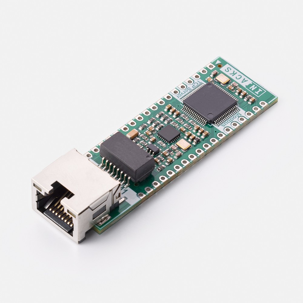
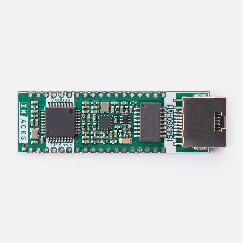
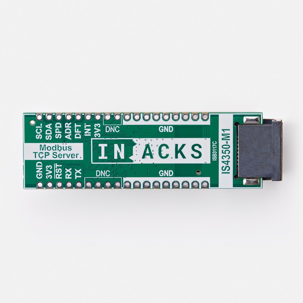
Modbus TCP server module with RJ45 connector. Turn any microcontroller with an I2C port into a Modbus TCP/IP server, without developing any TCP/IP or Modbus stack.
Modbus TCP/IP Server:
– Holding Registers: 65,500
– Function codes: 03, 06 and 16
– Port 502, one client connection
– IP address: DHCP (default) or static
Ethernet:
– Speed: 10/100 Mbps
– On-board LAN8742A PHY, magnetics and ESD protection
– RJ45 with link/activity and speed LEDs
I2C Interface:
– Slave addresses: 24, 25, 26 (7-bit, ADR pin)
– Speeds: 100 kHz, 400 kHz, 1 MHz
– Pull-ups: 3.3 V or 5 V
– No libraries required
Safety:
– Optional I2C CRC protection
– Optional I2C watchdog timer
– Fail-safe power-up
Module:
– Power supply: 3.3 V
– Size: 20 × 62 mm, 36 castellated pads, 2.54 mm pitch
– Operating temperature: −40 °C to +85 °C
Out of stock
The IS4350-M1 is a ready-to-use Modbus TCP server module that turns any microcontroller with an I2C port into a Modbus TCP/IP server. The board integrates the IS4350 I2C Modbus TCP/IP Server IC, the LAN8742A 10/100 Ethernet PHY and the Ethernet magnetics. It also includes ESD protection and an RJ45 connector with status LEDs, all pre-designed and tested.
Designing an Ethernet interface from scratch requires a PHY, its reference clock and its strap configuration. It also requires impedance-controlled RMII and MDI routing, magnetics, line termination and a shielded RJ45 connector. The IS4350-M1 contains all of this. Your design only has to provide 3.3 V, two I2C lines and a few configuration pins. The module then takes care of the Ethernet link, the TCP/IP stack and the Modbus protocol.
As a result, this Modbus TCP server module saves you from developing any TCP/IP or Modbus stack. You do not need to design any Ethernet hardware either. In addition, the module has 36 castellated pads on a 2.54 mm pitch. You can solder it directly onto your PCB as a surface-mount component, or fit pin headers for prototyping and evaluation.
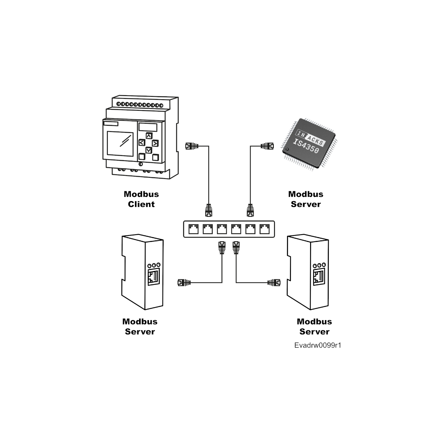
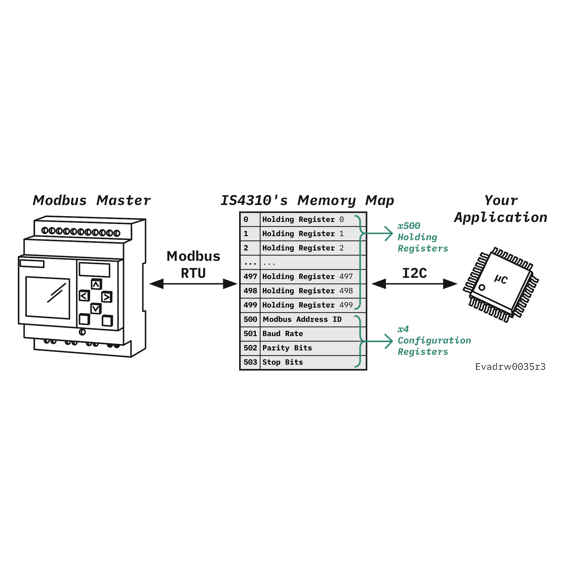
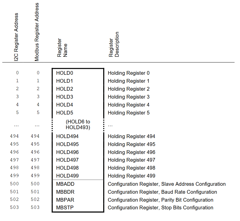
The IS4350 implements the complete Modbus TCP/IP server. It exposes 65,500 Holding Registers that your microcontroller and any Modbus client can read and write. The Modbus client can be a PLC, a SCADA system, an HMI or a PC. The Holding Registers work as a shared memory. Your firmware writes measurements for the client to read, and it reads the set-points and commands that the client writes.
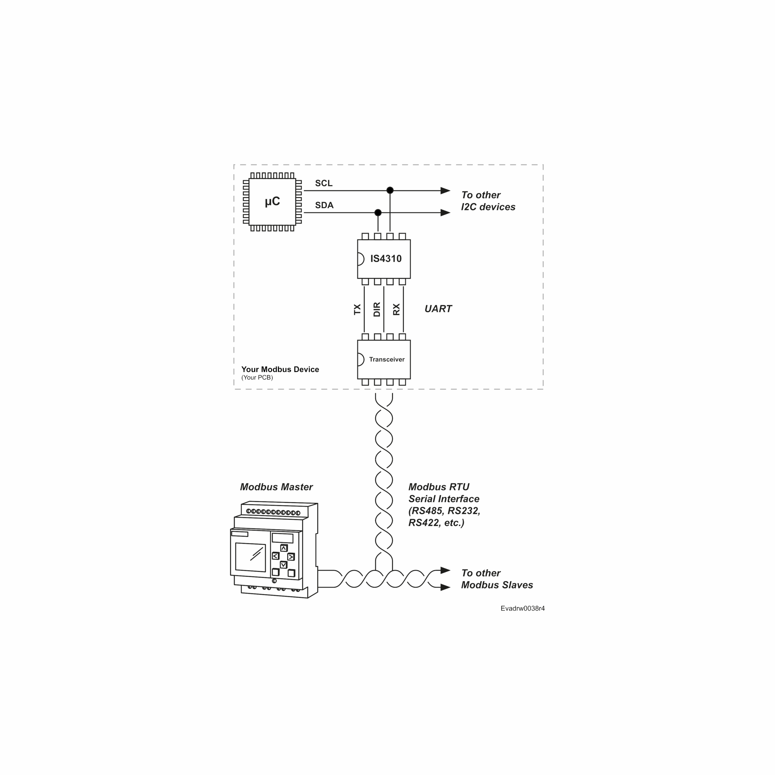
From your microcontroller’s point of view, the IS4350-M1 behaves like an I2C memory with 16-bit addresses and 16-bit registers. Therefore, you do not need any Ethernet driver, TCP/IP stack or Modbus library: standard I2C reads and writes are enough. For example, a temperature sensor writes its reading to Holding Register 0 (HOLD_0) and keeps it updated.
At power-up, the Modbus server stays offline until your firmware starts it. First, write valid data to your Holding Registers. Then, write 1 to the GO_ONLINE register (address 65513) and wait until the STATUS register (address 65514) reports 5: the server is ready and listening on port 502.
By default, the module uses DHCP and a MAC address generated from the IS4350 serial number. Consequently, no network configuration is needed. You can also set a static IP address, subnet mask and gateway over I2C or Modbus.
The Modbus TCP server module also includes several safety mechanisms for industrial products:
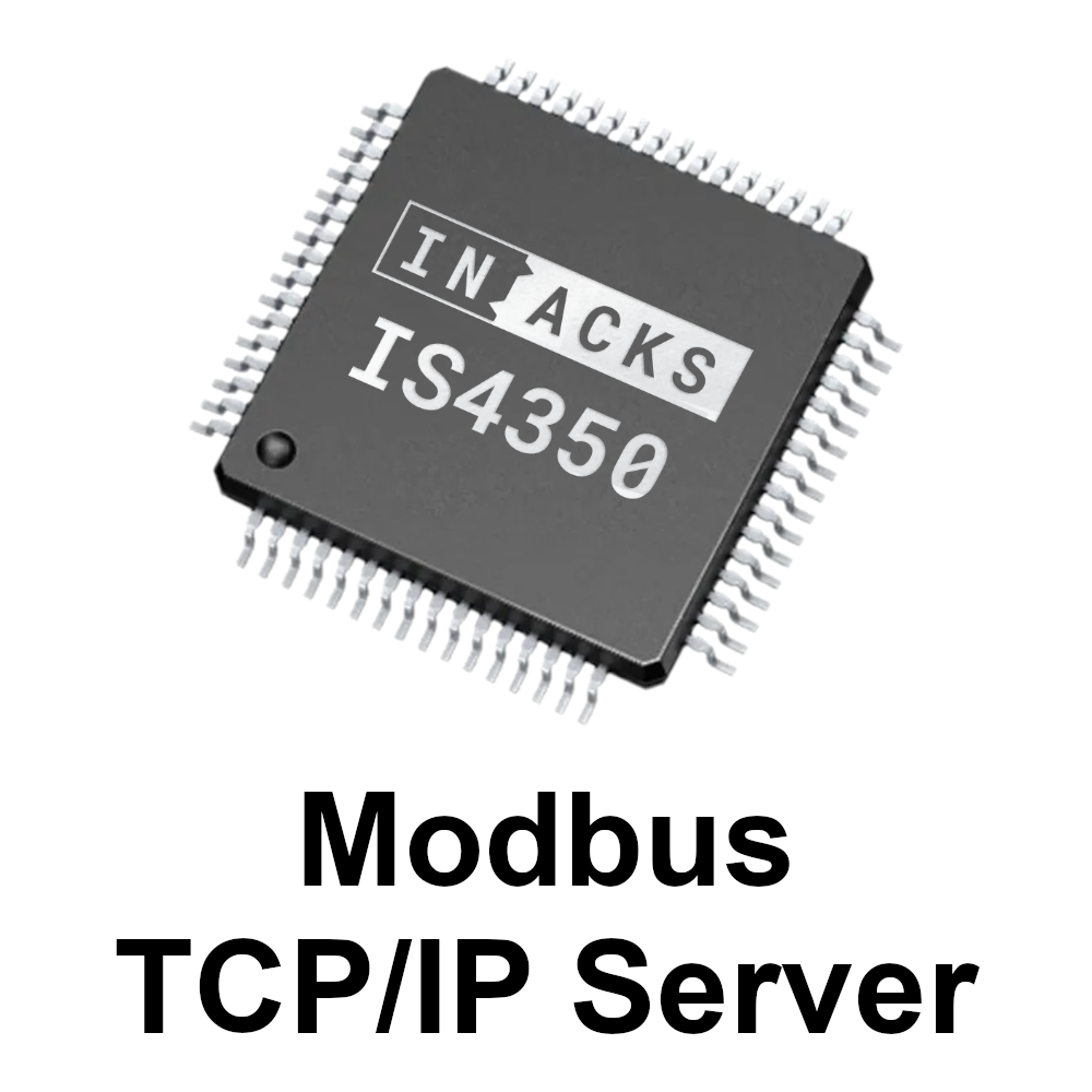
Do you prefer to integrate the Ethernet hardware on your own PCB? The IS4350 is also available as a chip in an LQFP64 package. It uses the same registers and the same I2C protocol, so your firmware works with both.
For the memory map, the I2C protocol, the I2C-CRC procedure and an Arduino example, see the IS4350 datasheet (ISDOC139).
This company and the products provided herein are developed independently and are not affiliated with, endorsed by, or associated with any official protocol or standardization entity. All trademarks, names, and references to specific protocols remain the property of their respective owners.
(This product includes the IS4350-M1 module. The 3.3 V power supply, the microcontroller and the Ethernet cable are not included.)
These external resources are not controlled or maintained by INACKS:
Q: What is the IS4350-M1 used for?
A: To add Modbus TCP/IP connectivity to any product with a microcontroller. Use it to build Modbus TCP/IP sensors and transmitters, actuator and motor controllers, remote I/O modules, energy meters, or building automation and HVAC controllers that a PLC, SCADA system, HMI or PC can read and control over Ethernet.
Q: Do I need a TCP/IP stack, a Modbus library or an Ethernet peripheral on my microcontroller?
A: No. The IS4350-M1 contains the complete Modbus TCP/IP server and all the Ethernet hardware. Your microcontroller only needs an I2C master that supports clock stretching. Any I2C driver can control it, for example the Arduino Wire library or the STM32 HAL.
Q: How does my microcontroller exchange data with the Modbus client?
A: Through 65,500 Holding Registers (HOLD_0 to HOLD_65499) that work as a shared memory. Your microcontroller reads and writes them over I2C, and the Modbus client reads and writes the same registers over Ethernet. For example, your firmware writes a temperature to HOLD_0, and the PLC reads it with function code 03.
Q: Which Modbus function codes are supported?
A: 03 (Read Holding Registers), 06 (Write Single Register) and 16 (Write Multiple Registers). The server listens on port 502 and accepts one client connection at a time. It responds to any Unit Identifier; the recommended value is 255 (0xFF).
Q: How do I read and write a register over I2C?
A: As with an I2C EEPROM. Register addresses and register values are both 16-bit, sent most significant byte first. To write a register, send the two address bytes followed by the two data bytes. To read it, send the two address bytes, then a repeated START, and read two bytes. Leave a few milliseconds between consecutive I2C operations. The IS4350 datasheet includes a complete Arduino example.
Q: How do I start the Modbus server?
A: At power-up, the server is offline. First, write valid data to your Holding Registers. Then, write 1 to the GO_ONLINE register (address 65513) and wait until the low byte of the STATUS register (address 65514) reads 5: the server is ready and listening. Write 2 instead of 1 to enable the I2C watchdog timer.
Q: How does the module get its IP and MAC addresses?
A: By default, it uses DHCP and a locally administered MAC address generated from the IS4350 serial number, so no network configuration is needed. You can also set a static IP address, subnet mask and gateway over I2C or Modbus, and you can set the MAC address manually or generate it randomly. Your firmware can read the current IP address from registers 65501 to 65504.
Q: What if a wrong network configuration makes the module unreachable?
A: Hold the DEF pin high for 3 seconds. The module restores the default network configuration (DHCP and the MAC address generated from the serial number) and restarts. In the final product, connect the DEF pin to a recessed push button to 3.3 V, so that nobody can press it by accident.
Q: Which microcontrollers are compatible?
A: Any microcontroller or microprocessor with an I2C master that supports clock stretching, such as Arduino, STM32 or ESP32. The I2C lines accept pull-ups to 3.3 V or 5 V, so 5 V boards such as the Arduino Uno need no level shifter. In that case, power the module before or together with the 5 V rail.
Q: Can I connect several modules to the same I2C bus?
A: Yes, up to three. The ADR pin selects the I2C address: 24 (GND), 25 (1.65 V, with two 10 kΩ resistors) or 26 (3.3 V). On the network, each module has its own IP address.
Q: Is the I2C communication protected against errors?
A: Optionally. Tie the CRC pin to 3.3 V to protect every I2C read and write with a CRC-16/Modbus checksum. The module discards any write with a wrong CRC, and your firmware can verify every read with the I2C_READ_CRC register. Keep the CRC disabled during development until basic communication works.
Q: What happens if my microcontroller stops working?
A: If you start the server by writing 2 to GO_ONLINE, the I2C watchdog timer is active: your firmware must write 2 again at least every 500 ms. Otherwise, the module stops the Modbus server automatically, so clients never read stale data. In addition, the server never comes online by itself at power-up.
Q: How many requests per second can it handle?
A: In INACKS tests, the IS4350 answered between about 216 and 270 Modbus requests per second, depending on the function code and on the number of registers. The real value depends on the network and on the Modbus client.
Q: What power supply do I need?
A: A single 3.3 V supply (2.7 V to 3.6 V) connected to both 3V3 pins. A low-noise regulator rated for at least 250 mA is a comfortable choice, with a 10 µF and a 100 nF capacitor close to the 3V3 pins. The 3.3 V pin of the Arduino Uno (50 mA maximum) cannot power the module.
Q: What is included?
A: The IS4350-M1 module. The 3.3 V power supply, the microcontroller and the Ethernet cable are not included.